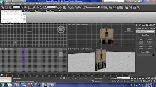
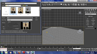
For my animation I need a building background, to do this I have follow the tutorial from the 3ds max 2011 tutorials.To begin making, I will need to change some of the setting first. To do this I click Customize, Preferences, on general tag make sure Use Real-World Texture Coordinates is off, then go to Viewports tab and click Display drivers, configure driver. The menu pop up and tick the Match Bitmap Size As Closely As Possible check box, by doing this I will need to restart 3d max to gain the effect.
To view the image in a pop up menu, I can go to rendering, view image file and choose the image I need. This will open a pop up menu contain the image I am working on and because this is a 3d max tutorial the image are made and store in 3d max already.
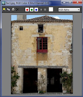
After the setting has change, I create a plane which has 8.7m length and 6.8m width. Then I change the pivot point to the base of the plane and convert to editable poly.
Instead of open compact material editor, I have use slate material editor. Drag Arch & Design to the active view, on the templates rollout, choose Matte finish. Then drag bitmap into the active view and open the image I need.
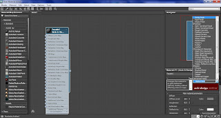
To join the bitmap with the Arch & Design, I have to drag the bitmap node’s output socket, which is the small circle at the right to link with the circle at the Arch & Design material’s Diffuse Color Map and Bump Map component.
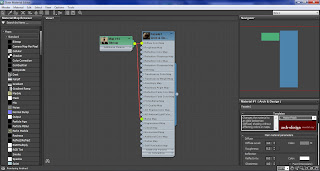
To apply the material, I have click on the plane and click Assign Material To Selection and turn it on, by clicking Show Map In Viewport.
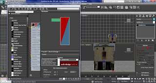
Apply UVW Map on the plane, so I can edit the plane poly surface without distorting the texture projected onto it. Then I apply poly select and make sure all the Show End Result is turn on.
Back to editable poly level and scroll down to subdivision surface rollout and change the second colour of the show cage to red, this will is easier to tell what part I have selected, because it will shown it red outline.
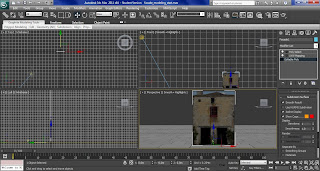
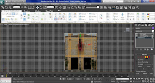
Make sure UVW Map are on the top of the modifier list, because if the UVW Map has place in the wrong order, the image will go wrong when using polygon tool. This has happen to me and take me a long time to fix the problem, as shown at the right.
Use the edge tool and select the top edge of the plane and move downward to hid the roof. Then turn on the swiftloop, add vertical and horizontal loops around the window, the lintel and doorway.
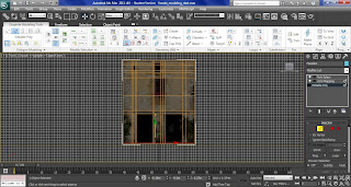
Click polygon and select the faces of the windows and use the extrude settings to extrude it to -0.05m, I then extrude the bigger window at the center with -0.1m height field and doorways with -0.6m.
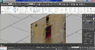
To extrude the lintel accurately, I will need to more the vertex to match the shape of the lintel in the image, also I have use the swift loop and cut tool to help me draw new edges, with cut tool I have starting on one edge and start drawing to match the shape. When is finish I simply extrude ans scale the lintel.
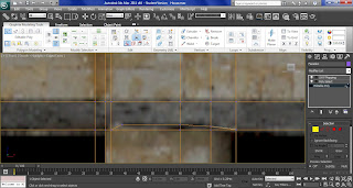
For the roof I have to click all the top edges using edge, to do this I have use Loop mode, this help me to select all the top edges in one click. Turn on select and move, then hold shift and move the Y-axis a bit forward, then move Z-axis until I can see the ends of the roofing tiles.
Click border and click the edge, this will highlight all the outside edge of the plane, then hold shift and move Y- axis of the border about 0.75m back. This create more depth to the roof area.
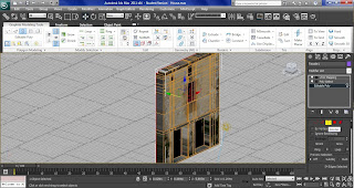
Change to edge and select all the edges at the rear of the roof and move the Z-axis until I can see the peak of the roof, then just move the vertex down to hide the sky.
As you can see the extrude in part has the over stretch effect, to fix this I have use unwrap UVW modifier.
On the Modifier list choose Unwrap UVW and from the plus-sign icon by the UVW entry choose face sub-object to active it. Start with the doorways click on the faces I want to change and go to map parameters rollout, click planar, then align x and make sure to turn of planar, otherwise I won't be able to use controls in the edit UVWs dialog.
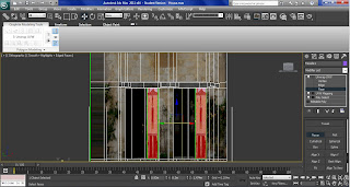
With the faces still highlighted go to parameters rollout, edit, the Edit UVWs dialog will pop up.
choose the image I am using the background pattern drop-down list. Turn on Filter Selected Faces and freeform mode, drage the corner to scale the face and move the box to the place I want, then I can use the mirror Horizontal to make the right image I need.
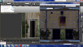
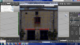
For the doorsteps, select the doorstep, then Map Parameters rollout, click Planar, and this time I use Align Z. Go to edit in the Parameters rollout and drag the corner of the box to match with the lintel beam. Then I apply the same technique to the windows and walls.
No comments:
Post a Comment