Tuesday 29 March 2011

Magic night

For the night time ocean, because I cant get perfect blue colour out of the Daylight system, so remove the colour from it. Select the Daylight, go to the Modify panel, mr Sky Advanced Parameters, red/blue tint and saturation to 0.
Select rendering, exposure control, mr Photographic Exposure Control, Image control, change the value of Colour Saturation to 1, this saturation of the colours of the whole image, Whitepoint to 3000, this change the colour temperature of the light source and Vignetting to 7, this adds vignetting effect to the image.


I can now add some floating light sources over the ocean, create a sphere, and have the radius of 0.3.
Open material editor, click get material and select Arch & Design from the list, on the main material parameters, Diffuse, colour to white, then go to Self Illumination(Glow), turn on self Illumination (glow) and Luminance to 1000. Assign the material to the sphere.


Now I need to change the mr Photographic Exposure Control setting, click rendering, environment, mr Photographic Exposure Control, change the value of Physical Scale: Unitless to 1500.
Create a Omni light and go to the modifly panel, multiplier to 20, decay, type to inverse square and start to 10. Place the Omni light to the middle of the sphere.
I want the moon and the sphere to have stronger glare, click rendering, render setup, renderer, camera effects, camera shaders, then open material editor and drag the glare shader to a material slot in the material editor. In material editor, change the spread value to 4, making the glare stronger.


Select Daylight, modify panel, mr Sky Parameters, Multiplier to 1.5, this make the moon darker.

Then I decide to animate the water, so I select the plane and apply the wave modifier from the modifier list, drag the time slider to 100 and turn on auto key. Click wave, change Amplitude 1 to 90 and Amplitude 2 to 19. Then click rendering, video post, select files in the dialog box, name it and save in .avi format. Select Execute Sequence Button and in the Time Output rollout, select range then render.


Reference:
polygonblog
2011
3D Water - The ocean
http://www.freeitsolutions.com/3ds/viewTutorial.aspx?id=4129
[Internet]
[27/3/2011]

Sunset ocean

To simulate sunset, I have place the sun near the horizon, this will change the colour and intensity of the image based on the angle of the sun. I can see the sun and illumination before rendering the image, first activate the camera view and press shift and F3, click views, viewport background, viewport background settings, turn on use environment background and display background.


Now I need to change the image to more orange, select the daylight and go to the modify panel, mr Sky Advanced Parameters, red/blue tint to 1.0 and saturation to 2.o. Next I am going to apply some glare to the sun, click rendering, render setup, renders, camera effects, camera shaders, turn on the output shader and glare.


I can apply some fog/haze to the scene to the image, by selecting the daylight, modify panel, mr Sky: Haze Driven (mr Sky), Haze to 2.0, this adds haze/fog to the scene. Then mr Sky Advanced Parameters, Aerial Perspective, visibility distance to 50, this makes the haze appear closer, and finally go to mr Sky Parameters, multiplier to 2.0, is increases the intensity of the sun to shine stronger behind the haze.

The ocean

For my animation I need to create a sea, to do this I create a plane with 500 length by 500 width. Create a target camera in the top viewport to the center of the plane and aim the camera slightly downward at the plane. Change the perspective view to camera view, so I can see what is happening to the from the camera view.

Open material editor, click get material and select Arch & Design from the list, from the drop down list of template choose water, reflective surface and assign the material to the plane.


Next I need to apply daylight to the ocean, to do this I go to the create panel, system, daylight and create it in the top viewport. Place the daylight at the top of the plane, so is shines straight from the top of the ocean.
At the daylight parameters, choose mr sun for sunlight, mr sky for skylight and position manual, which allow me to place the sun manually, instead of using real word loctaion and time.
Now if I render the ocean is OK, but I still need to improve it, like the horizon need to be lower, smaller waves, the colour of the ocean and brighter image.

To lower the horizon, I need to select the daylight and go to the modify panel, mr Sky Advanced Parameters, Horizon and enter a value for the height(eg -0.3).


For smaller and bluer ocean waves, I need to go back to the material editor. At the main material parameters change the colour to blue, go to the special purpose maps, click (ocean(lume)) shader and change the largest to 2.5 and smallest to 0.12.


Now I need to brightness the image by changing the setting of the light, select daylight and go to the modify panel, mr Sky Parameters, multiplier: 1.1, this increase the intensity of the sun, then mr Sky Advanced Parameters, red/blue tint: 0.1 and saturation: 1.3, this changes the hue and saturation of the light and sky.

Then I apply a teapot and a torus knot to see how object look in the water.

Monday 28 March 2011

The history of MI6


MI6 was created from the secret service bureau in October 1909. The Secret Service Bureau was renamed SIS in 1911, the first head of SIS was captain Mansfield Cumming and used C as a code name. Since then every director of MI6 used the initial C.

Reference:
Mr. E
2011
The history of MI6
http://www.topspysecrets.com/mi6-history.html
[Internet]
[23/3/2011]

Using daylight


I want to add some daylight for the MI6 building I created, so I click create, lights and daylight system. At the top view drag the size of the compass at set the height of the light are going to be.
From the control parameters, I can set the time, date and location of the light.


Click modify, Daylight parameters, choose mr sun for sunlight and mr sky for skylight. If I want to change the time of the light, I can go to position and click setup.

MI6

Using what I learn from the 3ds max 2011 tutorials, I have decided to make the MI6 building.
First I find the front view of the MI6 image and change what I don't need in photoshop.

In 3d max I create a plane, set the length and width same as the image. Open slate material editor, drag Arch & Design to the active view, choose Matte finish in the templates rollout, then drag bitmap into the active view and open the MI6 image and link with the circle to the Diffuse Color Map and Bump Map component at the Arch & Design material’s. Turn on show map in viewport, and drag the Arch & Design material node’s output socket to the plane.

Use the select and uniform scale tool, to scale the plane to the size I want, change the pivot to the base of the plane and convert to editable poly.
Apply UVW Map and poly select, go to the editable poly level, click edge and select the top edge of the plane, move the edge downward to the first level of the building, hold shift and drag the move Y- axis backward and move the edge up, and repeat this for each level, so this has create the floor for each level of the building.


To create depth for the windows and surface, I have turn on swiftloop, to add vertical and horizontal loops around all the windows and the surface of the building, select polygon to highlight the windows and use extrude settings and in height have the value about -2. For the surface part of the building I just extrude it outward.


Select border and click the edge, this highlight all the outside edge of the plane, then hold shift and move Y- axis of the border back.

As you can see each floor of the building has been over stretch, so I apply unwrap UVW modifier, choose face sub-object from Unwrap UVW and select the faces that are over stretch.


Go to map parameters rollout, click planar, then align z, go to parameters rollout, edit, the Edit UVWs dialog will pop up. Turn on Filter Selected Faces and freeform mode, drage the corner to scale the face, move and rotate the box to the size and place I want.


Reference:
David Williams, Charlotte Gill and Tom Kelly
2010
Did spy's killer steal state secrets? MI6 agents search for 'missing' laptop or MP3 player after body-in-bag murder case
http://www.dailymail.co.uk/news/article-1306233/Did-killer-MI6-spy-Gareth-Williams-steal-state-secrets.html
[Internet]
[23/3/2011]

Wednesday 23 March 2011

Add wind to the cloth

To add wind to the animation, drag create wind from the reactor toolbar to the viewport, then rotate to the direction I want. Go to the modifier panel and change the wind speed.

Cloth

Create a plane with 10 by 10 segments for the cloth, a lone cylinder for the pole and 5 tube for the hooks.

Click on the plane and drag the apply cloth modifier and cloth collection to the viewport, from the reactor cloth click on the plus-sign icon and choose vertex, go to constraints rollout, click attach to rigid body, rename it and click on the vertices, so they turn red. In the attach to rigidbody rollout click none and select the hook in the scene.


Turn on auto key, just move each hook in different time, so it set out different keyframe in the timeline.
Preview the animation and pree p.

Reference:
Carol Batton
sunset
2011
http://www.maroonedonline.co.uk/613
[Internet]
[23/3/2011]

Reactor

The reactor can be access by going to utilities, reactor. To get the reator tool bar to show up, find a space at the menu bar, right click and reactor.

Then I create 8 sphere and a box. Click on one of the sphere and drag the create rigid body collection to the viewport, this will include the sphere I have clicked to the collection, to include the rest of the object, I click add, the select rigid bodies menu will pop up, click on all the objectand press select, so now all the object is included.


Now I have to add some mass, for the three sphere that I am going to drop down, so click open property editor, physical properties, mass and change the value for the spheres. At simulation geometry, click bounding sphere.


Click preview animation, and p to play the animation.

Tuesday 22 March 2011

Building part 2

Create a plane with 10m length and 6.8m width, move the the pivot point to the base of the plane and convert to editable poly.

Open Slate Material Editor, drag the Arch & Design to the active View, on the templates rollout, choose matte finish from the drop-down list of templates. Then drag bitmap to the active view and open the second building image, wire the bitmap to the Arch & Design material’s Diffuse Color Map and Bump Map components. Turn on show map in viewport, and this time just drag the Arch & Design material node’s output socket to the plane.


Add UVW map modifier and poly select modifier to the modifier list. Use swift loop and create a vertical edge at the center, then use vertex, drag the upper-left and upper-right vertices down to match the roofline.


Turn on edge and click the two roof edges, then move them down to hid the cornice.
Use swift loop to add some vertical edges for the windows, but this time I cant use swift loop to add horizontal loops, because of the peaked roof, so I have to use quickslice, position the cursor at the horizontal top of the upper window, and click the mouse twice to set the quick slice. Then I just repeat for the lower window and after horizontal loops is added, I can now use swift loop to create horizontal loop.


For the arch I have turn on swift loop again and add some vertical and horizontal loop around the arch. Then turn on cut to draw the outline of the arch, by joining with the vertical edges.


Click polygon and select the faces in the archway, hold shift and click extrude to display the extrusion caddy, in the height field enter -0.3m. Instead of clicking ok, click apply and continue, enter -0.4m for the second extrusion. Then I extrude the windows is well.


For the roof it is similar to the first building, use edge to highlight the top edges, hold shift and move the edges forward a bit with the Y-axis, then up a bit with the z-axis, repeat the same for the second layer until I can see the cornice.

Apply Unwrap UVW to the Modifier List choose face from the plus-sign icon, click all the doorstep upper faces, go to map parameters rollout, click planar, then click align Z.
Click edit from parameters rollout. Choose the image from the background patten drop-down list. Turn on filter selected faces and freeform mode, and drag the corner to scale the size with the windowsill.

Hold ctrl and click to select the outer faces inside the archway, go to map parameters rollout and instead of using planar, this time I use cylindrical and click align y.
Use the select and rotate tool and change the Y-axis until the seam segment (green line) is at the bottom of the scene, and click fit.


Go to edit in the Parameters rollout, scale to the wall faces, so is cover a strip of stone above the arch and click mirror horizontal.
On the options panel, turn on vertex sub-object mode, on the menu bar choose tools and sketch vertices. From the sketch tool dialog, choose free form from the align to drop down list and turn on interactive mode.


With the pencil cursor, click the middle vertex, drag to the left to highlight the rest of the vertices, then just click on the top of the arch and draw down to lower left edge of the arch. This will make the vertices follow the line I have draw, then I do the same to the right and the top.


Monday 21 March 2011

Building


For my animation I need a building background, to do this I have follow the tutorial from the 3ds max 2011 tutorials.To begin making, I will need to change some of the setting first. To do this I click Customize, Preferences, on general tag make sure Use Real-World Texture Coordinates is off, then go to Viewports tab and click Display drivers, configure driver. The menu pop up and tick the Match Bitmap Size As Closely As Possible check box, by doing this I will need to restart 3d max to gain the effect.

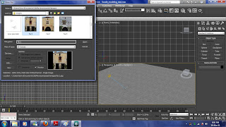
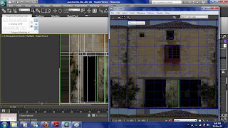
To view the image in a pop up menu, I can go to rendering, view image file and choose the image I need. This will open a pop up menu contain the image I am working on and because this is a 3d max tutorial the image are made and store in 3d max already.


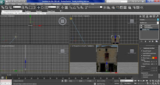
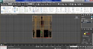
After the setting has change, I create a plane which has 8.7m length and 6.8m width. Then I change the pivot point to the base of the plane and convert to editable poly.

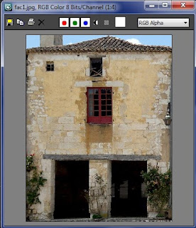
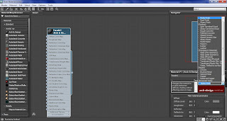
Instead of open compact material editor, I have use slate material editor. Drag Arch & Design to the active view, on the templates rollout, choose Matte finish. Then drag bitmap into the active view and open the image I need.


To join the bitmap with the Arch & Design, I have to drag the bitmap node’s output socket, which is the small circle at the right to link with the circle at the Arch & Design material’s Diffuse Color Map and Bump Map component.


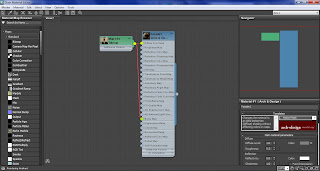
To apply the material, I have click on the plane and click Assign Material To Selection and turn it on, by clicking Show Map In Viewport.


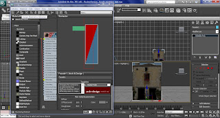
Apply UVW Map on the plane, so I can edit the plane poly surface without distorting the texture projected onto it. Then I apply poly select and make sure all the Show End Result is turn on.

Back to editable poly level and scroll down to subdivision surface rollout and change the second colour of the show cage to red, this will is easier to tell what part I have selected, because it will shown it red outline.


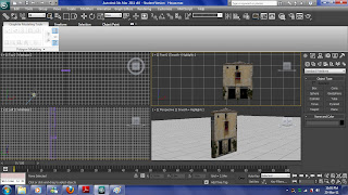
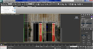
Make sure UVW Map are on the top of the modifier list, because if the UVW Map has place in the wrong order, the image will go wrong when using polygon tool. This has happen to me and take me a long time to fix the problem, as shown at the right.


Use the edge tool and select the top edge of the plane and move downward to hid the roof. Then turn on the swiftloop, add vertical and horizontal loops around the window, the lintel and doorway.


Click polygon and select the faces of the windows and use the extrude settings to extrude it to -0.05m, I then extrude the bigger window at the center with -0.1m height field and doorways with -0.6m.


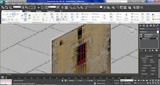
To extrude the lintel accurately, I will need to more the vertex to match the shape of the lintel in the image, also I have use the swift loop and cut tool to help me draw new edges, with cut tool I have starting on one edge and start drawing to match the shape. When is finish I simply extrude ans scale the lintel.


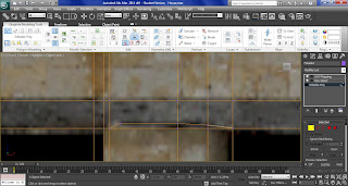
For the roof I have to click all the top edges using edge, to do this I have use Loop mode, this help me to select all the top edges in one click. Turn on select and move, then hold shift and move the Y-axis a bit forward, then move Z-axis until I can see the ends of the roofing tiles.
Click border and click the edge, this will highlight all the outside edge of the plane, then hold shift and move Y- axis of the border about 0.75m back. This create more depth to the roof area.


Change to edge and select all the edges at the rear of the roof and move the Z-axis until I can see the peak of the roof, then just move the vertex down to hide the sky.

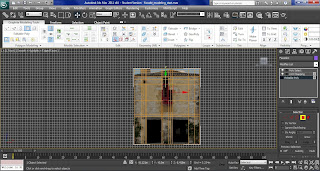
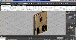
As you can see the extrude in part has the over stretch effect, to fix this I have use unwrap UVW modifier.
On the Modifier list choose Unwrap UVW and from the plus-sign icon by the UVW entry choose face sub-object to active it. Start with the doorways click on the faces I want to change and go to map parameters rollout, click planar, then align x and make sure to turn of planar, otherwise I won't be able to use controls in the edit UVWs dialog.


With the faces still highlighted go to parameters rollout, edit, the Edit UVWs dialog will pop up.
choose the image I am using the background pattern drop-down list. Turn on Filter Selected Faces and freeform mode, drage the corner to scale the face and move the box to the place I want, then I can use the mirror Horizontal to make the right image I need.


For the doorsteps, select the doorstep, then Map Parameters rollout, click Planar, and this time I use Align Z. Go to edit in the Parameters rollout and drag the corner of the box to match with the lintel beam. Then I apply the same technique to the windows and walls.