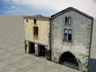
 Create a plane with 10m length and 6.8m width, move the the pivot point to the base of the plane and convert to editable poly.
Open Slate Material Editor, drag the Arch & Design to the active View, on the templates rollout, choose matte finish from the drop-down list of templates. Then drag bitmap to the active view and open the second building image, wire the bitmap to the Arch & Design material’s Diffuse Color Map and Bump Map components. Turn on show map in viewport, and this time just drag the Arch & Design material node’s output socket to the plane.
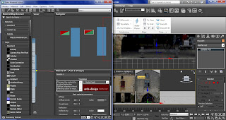
Add UVW map modifier and poly select modifier to the modifier list. Use swift loop and create a vertical edge at the center, then use vertex, drag the upper-left and upper-right vertices down to match the roofline.
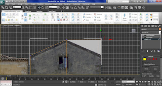
Turn on edge and click the two roof edges, then move them down to hid the cornice.
Use swift loop to add some vertical edges for the windows, but this time I cant use swift loop to add horizontal loops, because of the peaked roof, so I have to use quickslice, position the cursor at the horizontal top of the upper window, and click the mouse twice to set the quick slice. Then I just repeat for the lower window and after horizontal loops is added, I can now use swift loop to create horizontal loop.
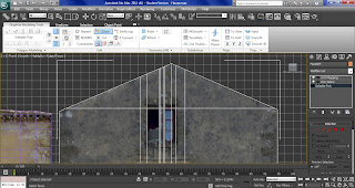
For the arch I have turn on swift loop again and add some vertical and horizontal loop around the arch. Then turn on cut to draw the outline of the arch, by joining with the vertical edges.
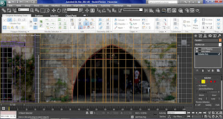
Click polygon and select the faces in the archway, hold shift and click extrude to display the extrusion caddy, in the height field enter -0.3m. Instead of clicking ok, click apply and continue, enter -0.4m for the second extrusion. Then I extrude the windows is well.
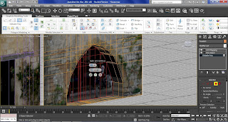
For the roof it is similar to the first building, use edge to highlight the top edges, hold shift and move the edges forward a bit with the Y-axis, then up a bit with the z-axis, repeat the same for the second layer until I can see the cornice.
Apply Unwrap UVW to the Modifier List choose face from the plus-sign icon, click all the doorstep upper faces, go to map parameters rollout, click planar, then click align Z.
Click edit from parameters rollout. Choose the image from the background patten drop-down list. Turn on filter selected faces and freeform mode, and drag the corner to scale the size with the windowsill.
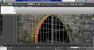
Hold ctrl and click to select the outer faces inside the archway, go to map parameters rollout and instead of using planar, this time I use cylindrical and click align y.
Use the select and rotate tool and change the Y-axis until the seam segment (green line) is at the bottom of the scene, and click fit.
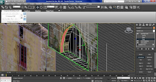
Go to edit in the Parameters rollout, scale to the wall faces, so is cover a strip of stone above the arch and click mirror horizontal.
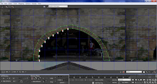
On the options panel, turn on vertex sub-object mode, on the menu bar choose tools and sketch vertices. From the sketch tool dialog, choose free form from the align to drop down list and turn on interactive mode.

With the pencil cursor, click the middle vertex, drag to the left to highlight the rest of the vertices, then just click on the top of the arch and draw down to lower left edge of the arch. This will make the vertices follow the line I have draw, then I do the same to the right and the top.
No comments:
Post a Comment